Howdy, this write-up isn't supposed to be a complete how-to but more of a reference for building and installing a Toyota third member. After reading and looking online I found a lot of good information, but still had questions! This is my attempt to answer those questions, giving everyone the confidence to build and install their own Toyota third member. I have built several at this point in my life, but am by no means an expert. Feel free to ask questions and i'lle try and answer them the best I can. Here are some links you might look at also: http://gearinstalls.com This first one is Zuk. He is the master at Toyota third members but recently stopped providing his services. His website still contains TONS if information. http://www.4x4wire.com This is a great write-up. Gives a lot of information, specs and tips for building the third. Even after looking at all of this I still had questions. I was still unsure of the little things. So here we go!
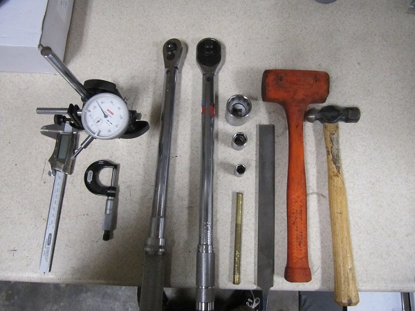
The first thing to know when doing this is, to do it right, you need the right tools. Without them you will work ten times as hard and know nothing about the quality of your work. On the plus side, none of the tools are expensive and are not job specific! Here are some of the tools you will need:
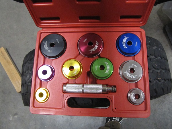
Calipers, Dial indicator with magnetic base, 3/8 toque wrench, 1/2 torque wrench, 30 mm socket, 17 mm socket, 12 mm socket, Brass drift, large clean file, Plastic dead blow hammer, hammer. I forgot to get pics (I will fix this) of a standard 3/8 ratchet, Large bearing puller, and 1/4 Inch bar style torque wrench. This 1/4 bar style torque wrench is really the only somewhat special tool that is needed. It can be bought from most bike shops for 20-30 dollars. Completely optional is a bearing race driver set. This one is from Harbor Freight and was around $20 dollars. Well worth it. I use it all the time on many different projects.
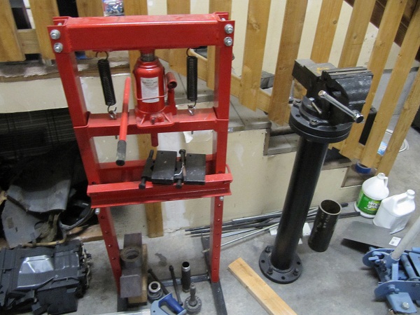
You will also need access to a press and vise.
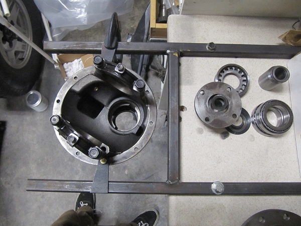
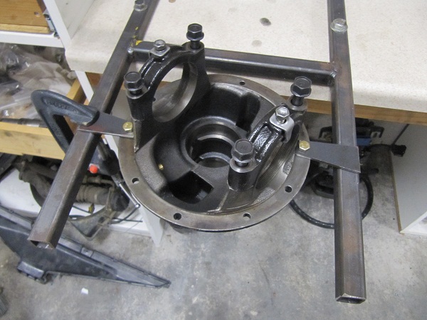
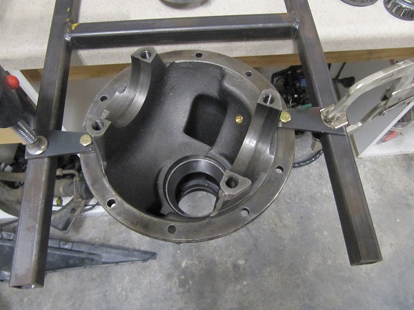
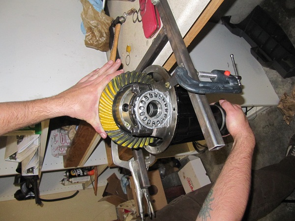
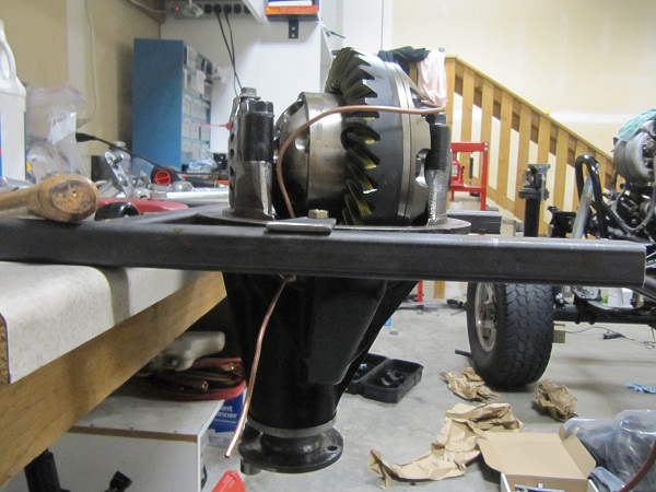
One suggestion I strongly make, MAKE A RACK to hold your work. It took me 10 min and saved me hours of struggling with a heavy third member. I made it out of 1" .125 wall square tubing, bolted to my work bench.
Another suggestion is to take some time and make some adjuster nut sockets. For a normal third member you only need to make one, if installing an ARB you will need to make two because ARB uses a special adjuster nut. They are easy to make and you can even buy them from different venders. They makes all the difference in getting the proper pre-load and guessing as you hammer the adjuster nut with a hammer and chisel. (I will posted beter pics of these when I get a chance)
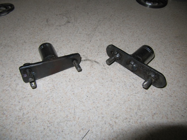
Left is for an ARB and the Right is a factory adjuster nut. I used some old bolts, old 1/2 sockets and welded them up. Works GREAT!
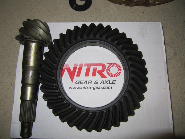
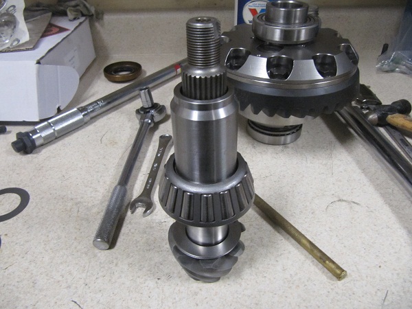
We are building a differential and need some parts! I started with a set of 5.29 Nitro Gears. The pinion came covered in cosmoline which needs to be clean off before you start. I used brake cleaner and a rage which took it right off. Which gear to use is the most asked question when doing this. I would recommend staying with a well known brand, Yukon, Nitro, Richmond, etc but most companies rebox gears so it's hard to know what you are really getting. Remember, a well set-up cheap gear will last longer then a poorly set up quality gear!
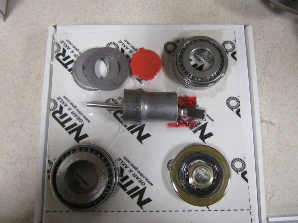
Nitro set-up kit. This comes with pinion shims, pinion bearing, seal, nut and crush sleeve. Normally this would also come with carrier bearings, but with the newer ARB's a special conversion bearing is needed.
Here is the ARB 132 and it's parts. This is the same unit sold for both 4cyl and V6 apllications.
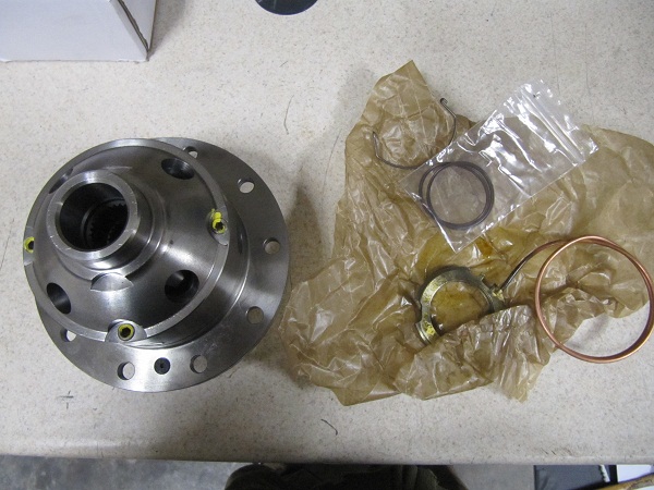
Here is a pic of the conversion bearings, This allows a V6 diff to be installed in a 4Cly housing. They work by having a V6, 50mm inner and a 4cy outer diameter.
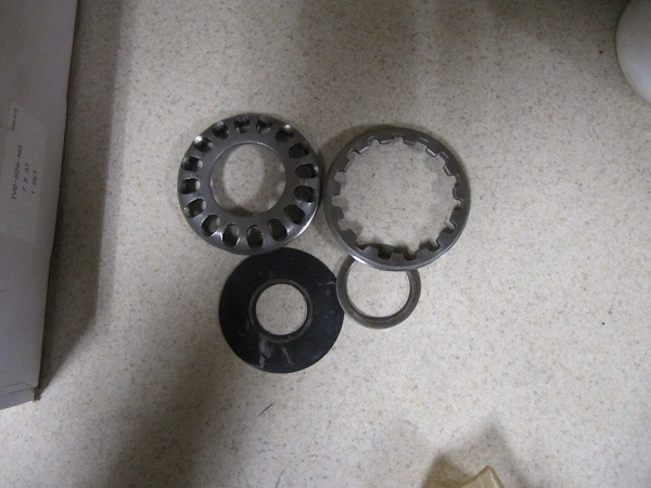
Here is a pic of the factory adjuster nut, ARB adjuster nut and oil retainer. When you purchase an ARB it comes with two adjuster nuts, one for V6 and one for the 4cyl. Use which ever one is needed. In my case it is the smaller 4cly nut.
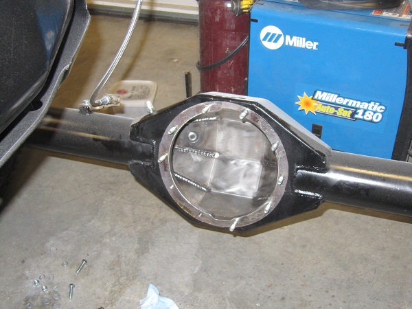
Here is the Empty housing with no bearing races installed.
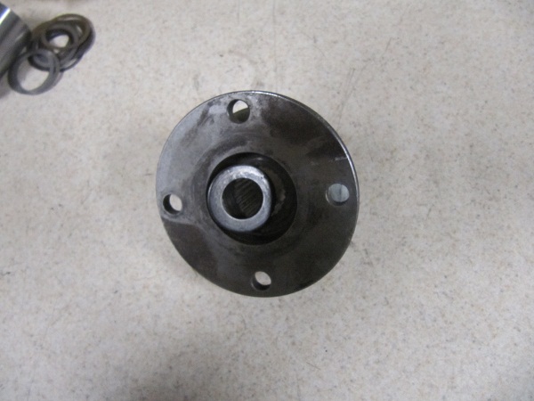
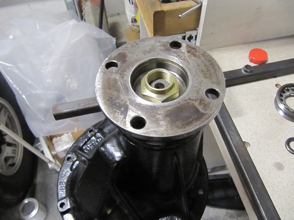
Drive flange and washer.
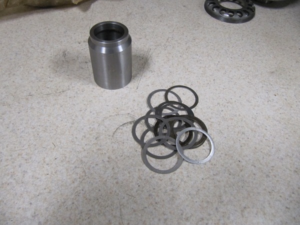
When you start reading and talking about Toyota third members the subject of crush sleeves Vs solid pinion spacer will always come up. I would always recommend a solid spacer. Its stronger and less likely to change over time or when you pound your drive flange on the rocks. Especially true in the rear differential. This write-up will cover only the install of a solid collar. Here is a pic of a solid color and it?s shims.
Finally you will need some chemicals. Oil, Aluminum anti-seize and Lock tight red. I like Valvoline but any quality oil will do. Also not shown it Gray RTV.

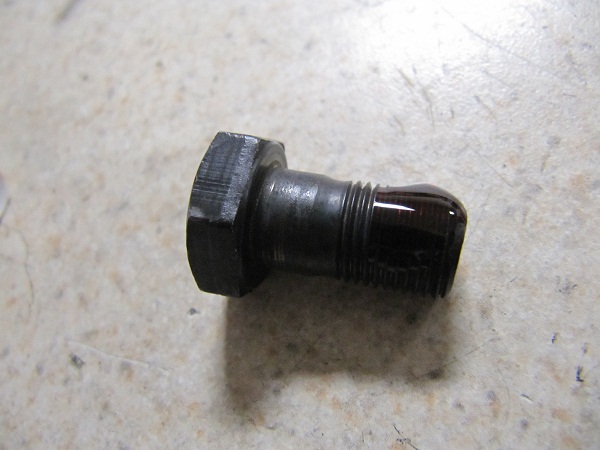
Start by running the file flat across the back side of the gear and mount flange on the ARB. This will show and remove any high spots. If you look at the back side of the gear I had several small bumps that I flattened out.


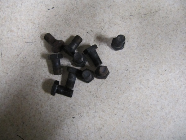
If reusing bolts, they need to be cleaned and try. Most setup kits come with new bolts.
Next is to get the gear onto the locker. This can be tough. An easy way is to place the gear in a 120 degree oven for 20 - 30 min, to expand it and the quickly take it out and slip it on the locker. Lining up the bolt holes. Sometimes a few good whacks with a plastic dead blow hammer will get it on. DO NOT HIT IT WITH A METAL HAMMER! You can even press it on, just be careful of the gear, using wood to keep it from any metal on metal contact. This gear went on with a few blows with the dead blow. (Sorry no Pics)
Once you have the gear on and bolt holes lined up its time to bolt her down. I placed the hole assembly into a vise lined with a towel (to keep it from getting scratched up) and tightened it down.
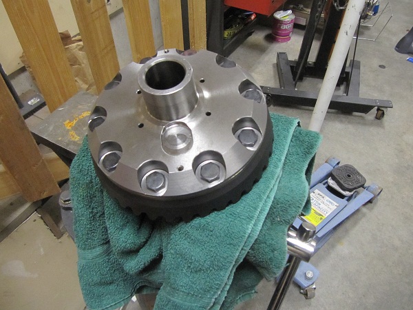
I then applied locktight red to the 10 bolts and threaded them into the gear.
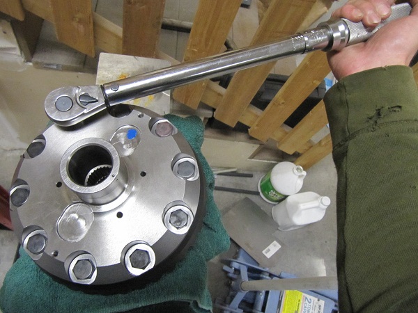
Then using my 3/8 torque wrench and 17mm socket I tightened them down to 80 ft lbs. I did this by using a criss cross patern in several progressively tighter stages.
Here we see the ARB seal housing side of the locker. Take care not to scratch this or your locker might leak!

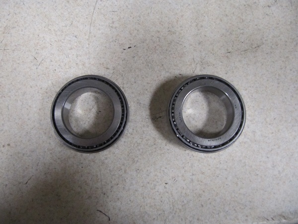
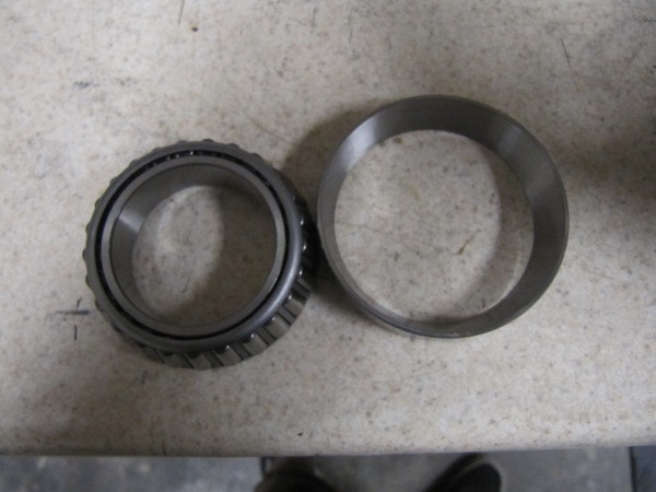
Now we can press our carrier bearings one. The bearing comes in two pieces, the bearing and its race. The bearing is what is pressed on and the race it added once in the housing. The bearing is pressed on tapper up!

Incase you don't have a lot of experience pressing on bearings, DO NOT press them on using the cage. This will cause the cage to flare out and the bearing to fall apart. Press against the small inside lip. A quick tip. Press the long side on first. So when you press the opposite side on, its not resting on the bearing cage.

It can be hard to find the perfect spacer to use while pressing. I have some old bearing races I ground out that I use. You will just have to look around and see what you can find.
If while pressing the bearing doesn't spin freely. Stop and find something else to press it on with.
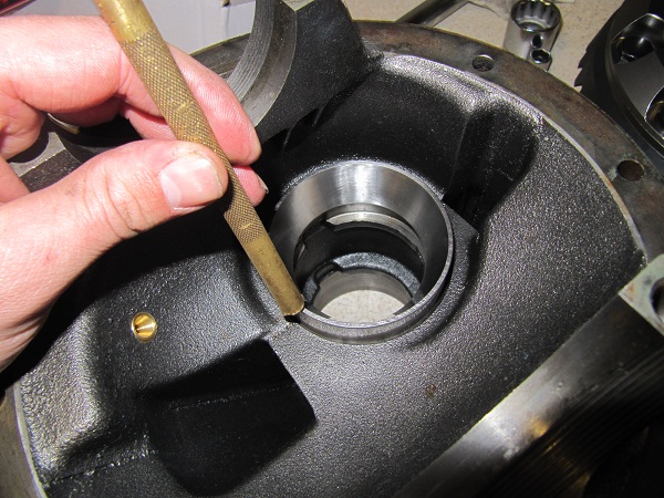
Next we turn our attention to the empty housing. Time to press in the new bearing races. You can use a brass drift or a race driver set if you have one. The soft brass or aluminum won't harm the hardened steel race. Make sure the tapper is pointing out.
Inner race
Outer race.
You know the race is fully seated when you feel and hear and solid clunk when you hit on it. Also visually inspect the race to make sure it looks ok.
We mounted it back in the holder. Notice the nice new races installed. You might also take note of the brass ARB airline plug which in installed at an earlier date.
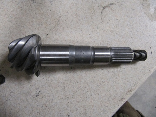
Now its time to turn out attention to the pinion. It was cleaned. If you don't clean the cosmoline off you will hate life. You will get incorrect measurments, patterns and a poorly setup Third member.
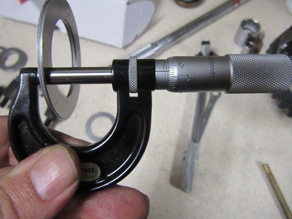
Here I am measuring my first shim pack. I like metric and have 1.98 mm or 0.077" of shims. This is a guess and each gear and housing will be different. It can take several attempts to get this number correct. This can be labor intensive and take along time and is why people pay others to set up their diffs.
Here you see where the shims sit between the pinion head and inner gear as well as how they move the pinion up and down in the housing. Next we will press the inner bearing on. Make sure the taper is going the correct way.
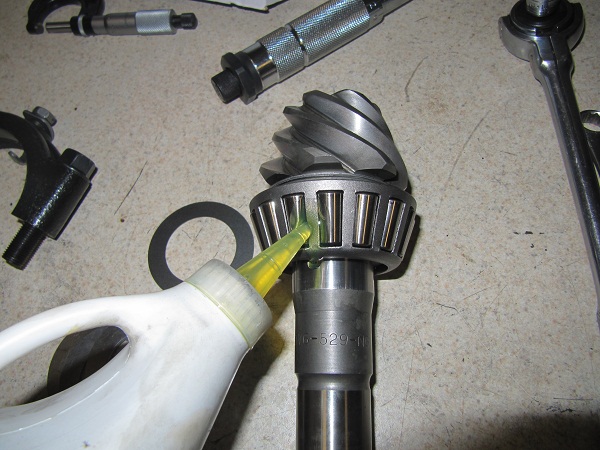
Once pressed on make sure you add lots-o-oil to the gear. Never spin a dry bearing!
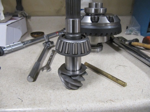
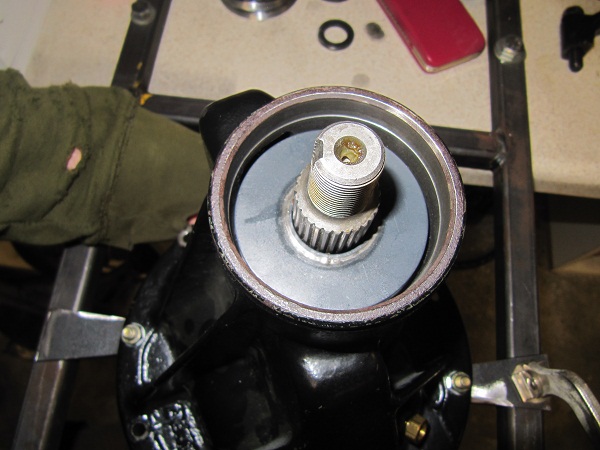
This shows you how the pinion sits in the housing.
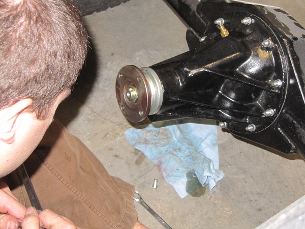
I flipped the housing over and while holding the pinion in place. I added the outer bearing, Oil retainer and flange.
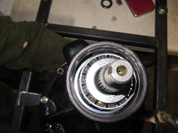
Now as you tighten the flange nut, it will press the outer pinion bearing on. Tighten this until you feel no up and down play in the flange, but the flange spins with not resistance. This is zero pre-load.
Preload is pressure against a bearing forcing it deeper into its race. This keeps the bearing tight and wearing properly through its life. As the bearing breaks in the bearing will loosen slightly but preload compinsates for this and keeps everything tight. If you don't add enough preload as the bearing brakes in the bearing will become to loose and fail. To much preload and the bearing could overheat and be subjest to excess wear. This is why used bearings need less preload then new ones. Used bears don't need the added preload to compensate for the bearing brake-in.
This "pre-load" can be measured by the rotational resistance caused by the compression of the bearings into its races. For new pinion bearings I would want to see at 12 - 16 in pounds of rotational resistance. This measurement should be taken as the pinion is spun at about 1 revolution a second. Remember to oil your bearings before spinning them! As you start to spin you will see the scale jump up and then settle down quickly. As you continue to spin this stable reading is your preload.

The next step is to get the carrier bearing caps on. This can take a little time to get right. I know of two ways to go about this. One is to take your time and by eye line the threads up. Tighten the caps down leaving them somewhat loose, coat the threads with a liberal coating of anti-seize and thread the bearing caps on. With the caps loose they will align themselves. DO NOT FORCE THEM. This will cross thread them.

The second method is to coat the top and bottom threads with anti-seize. Thread the carrier bearing cap into the bottom/housing threads.
Next install the upper cap and thread the bolts in a few turns. Next tap the top of the cap with the handle of a hammer or with your first until the cap is seatted. This will align the threads and seat the cap.
Don't forget both sides!

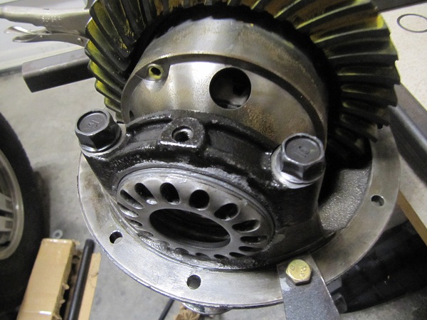
Snug the cap bolts down, but not overly tight. Now it is time to set the backlash!
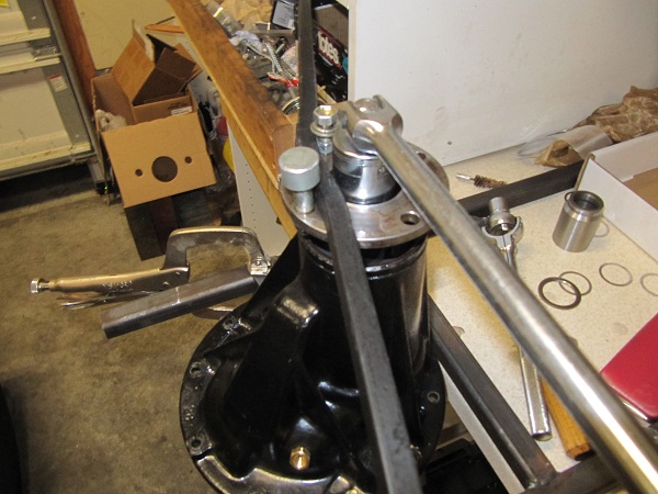
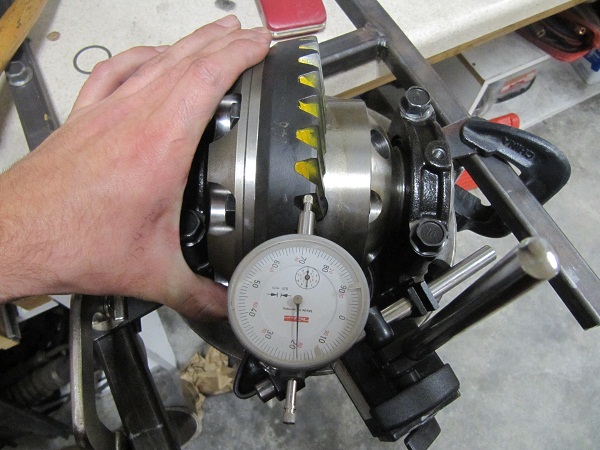
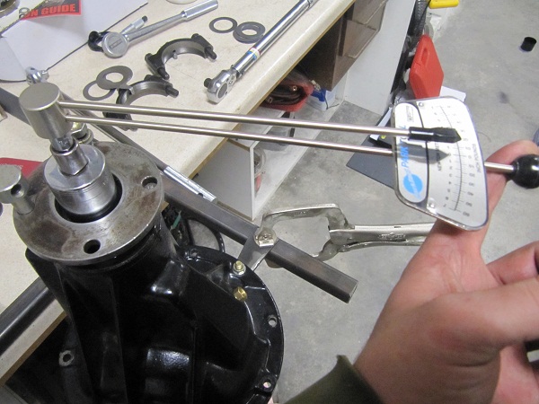
Backlash is a measurement which determines how close/deep the ring gear sits to the pinion gear. It is measured with a dial indicator from the face of the ring gear. Gently rock the ring gear back and forth and the measured difference is your backlash. The rocking motion should take very little effort and you should see no movement of the pinion.
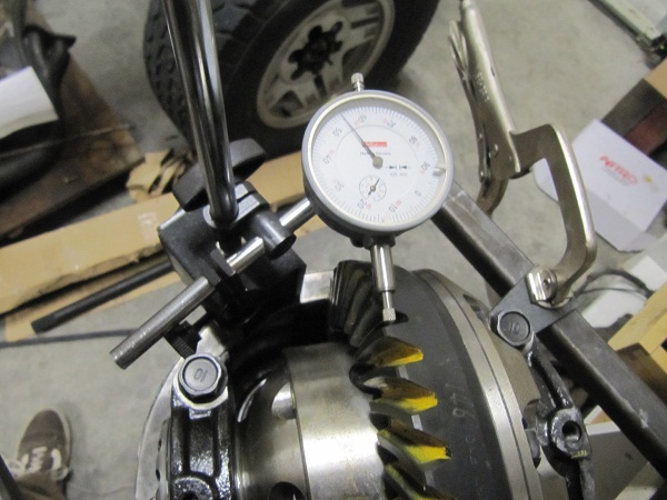
Here we have set out dial indicator with magnetic base on the edge of our housing and positioned it so it sits as square as possible to the ring gear face. Make sure that the dial indicator is not resting or touching in places other then the base and tip. Make sure you attach the base to the housing and not the stand. This can cause inaccurate readings.

This is by far the most difficult part of this process and can take some time to get the hang of it. The idea is to slowly tighten/loosen the carrier bearings which move the ring gear in and out until the desired backlash is reached. The ring gear side adjuster will increase the backlash the the opposite side adjuster will decrease it.
The procedure I use for this is to tighten the ring gear side until I see the ring gear move away from the pinion a noticeable amount. This seats the ring side carrier bearing into its race. Now loosen the same adjuster several turns. Now check the backlash, you will have way to much. Slowly begin to tighten the opposite side adjuster, checking the backlash after each adjustment. You will see the backlash slowly decreases. Continue this process until you reach the desired backlash. For me this is .20 mm or .008". Once this is achieved tighten the gear side cap until it is snug. Recheck the backlash.
If you now have to much backlash you will need to loosen the gear side adjuster and tighten the opposite side. This back and forth can take several tries to get correct. As you are doing this the carrier bearing caps should spin without much force. If the caps begin getting tight and you really have to use force on them you are adding preload to the bearings. This isn't what you want at this point, simply loosen the adjusters and try again.

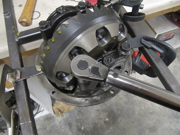
Now that you have the desired backlash, its time to add some preload to the carrier bearings. Slowly tighten both adjuster nuts with a 1/2 torque wrench and the adjuster nut tools pictured above. For pattern checking I tighten my carrier bearing adjuster nuts to 40 - 60' lbs. Rechecking your backlash constantly and making any adjustments needed to keep it where desired.

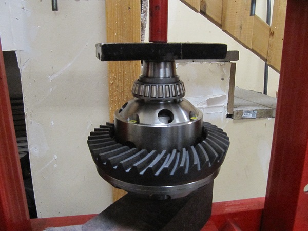
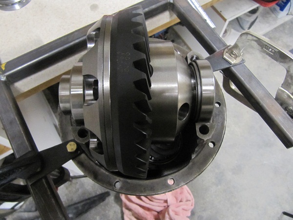
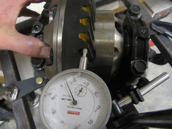
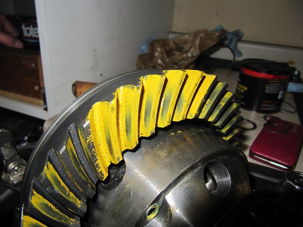
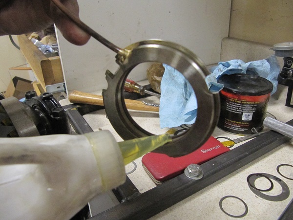
Now we can finally see if all out work was worth it. In your install kit should be a small brush and gear paint. Paint several gears front and back solid with the paint.
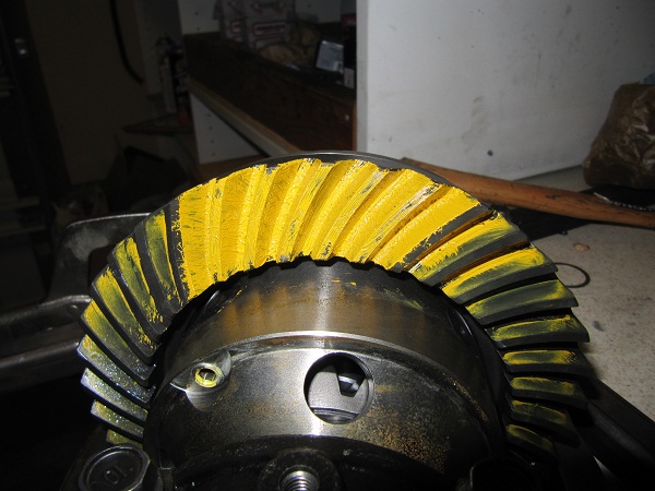
Now while appling some pressure to the ring gear, spin the pinion flange until the painted gears have contacted the pinion. Now spin the pinion the opposite direction. Keep rotating until the marked gears have reach the top and take a look.
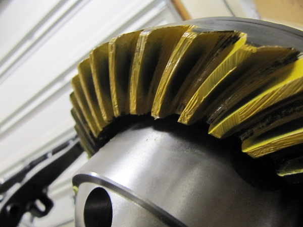
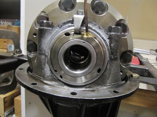
So now what. Depending on your pattern you might almost be done. This pattern is very close but is still a little deep. I know a great many people that would call this good enough and move on. But not me. To change this pattern we must increase or decrease the amount of shims between the pinion and inner bearing. If your pattern looks good move on down to final assembly. Here is a simple chart that shows different paterns and the causes.
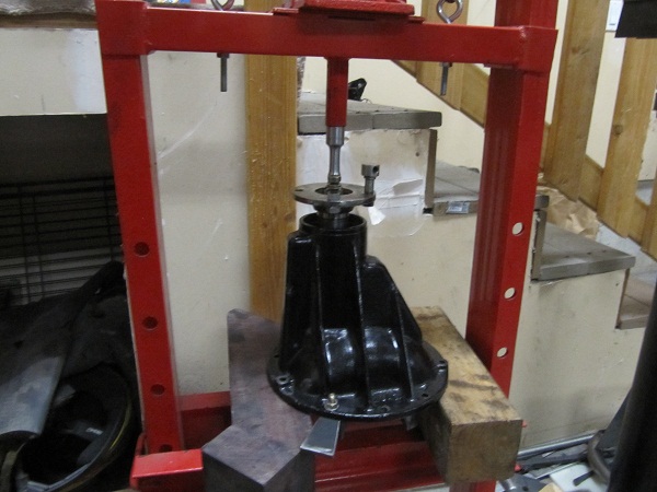
Start be removing the bearing caps and ring gear assembly. I know all that work for nothing. Flip the housing over and remove the Pinion nut and flange. Now using a press, press out the pinion from the housing. You might want to put some shop rags inside the housing to catch the pinion when it brakes free.
Now we will press off the inner pinion. The inner pinion is a big bearing and this can be a pain to do. The better quality bearing separator you have the easier this will be. I have a cheap harbor freight one and this process cost me some shims.
Take the bearing splitter and place it between the pinion head and bearing. Tighten down the bearing splitter until it is catching on the inside bearing race. DO NOT PRESS IT AGAINST THE CAGE. This can cause the cage to fail and you will be buying a $30 bearing.
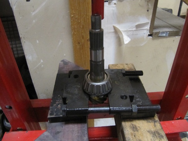
Now press it off. While tightening the bearing splitter I deformed some of the shims I used. This is ok to me and the price of doing business. If this bothers you, you can buy or make a set of setup bearings, which are slip fit and not press fit.

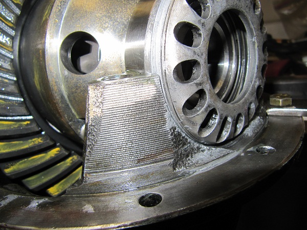
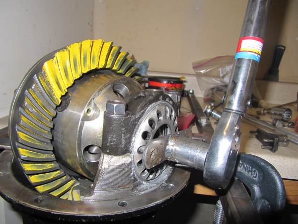
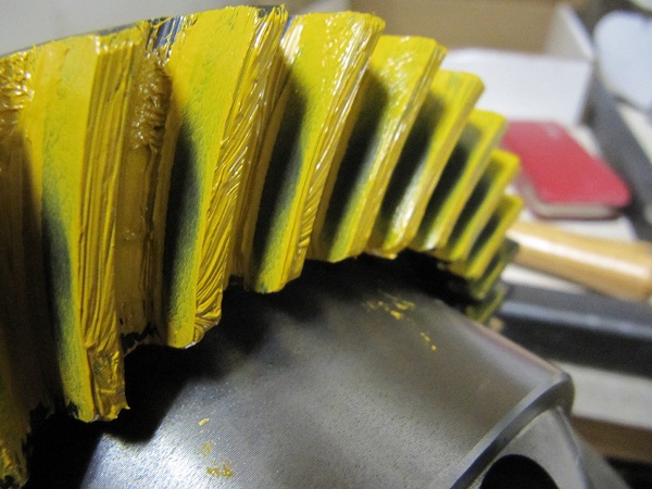
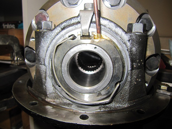
Now we subtract .06 mm or 0.002 in from the shim pack for a total thickness of 1.92 mm or 0.075 in and repeat the hole process! And WALA!
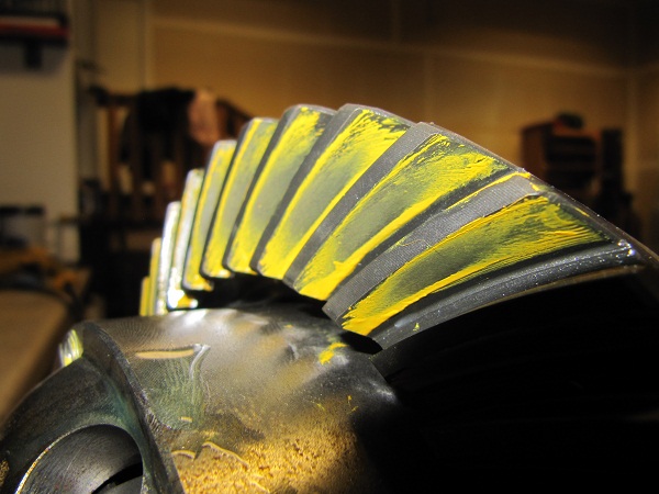
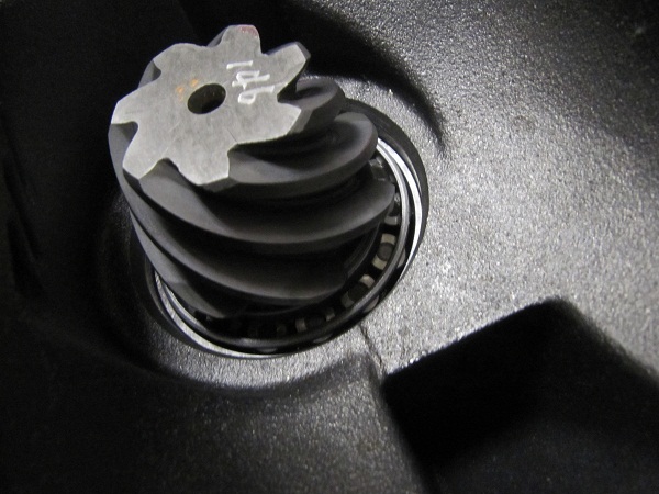
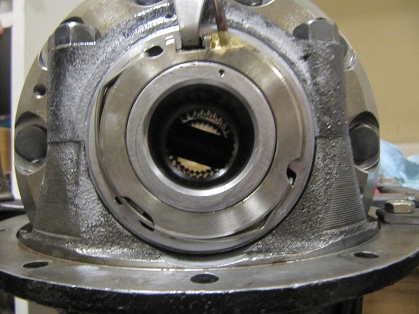
This pattern looks great to me. :P
Now sadly we get to take it all apart again to set up the solid spacer and final install. But I promise we are on the down hill side.
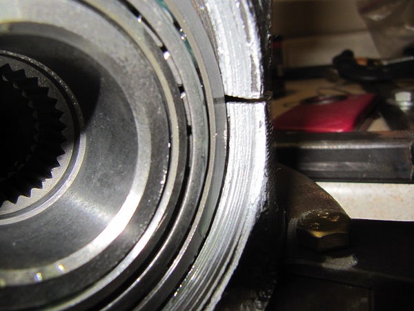
Once the ring gear assemble is removed press the pinion out of the housing as we did before. Now install the solid spacer between the inner and out of the bearing. Add a small amount of shims on top the solid spacer and install the outer bearing, flange and flange nut as we did before. (Sorry this is the best pic I have.)
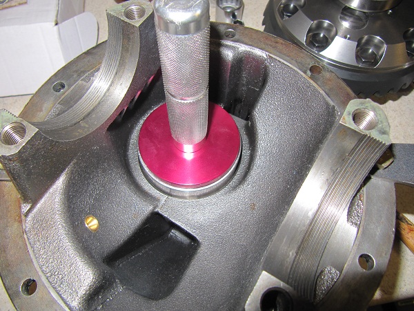
Now torque this pinion nut to 120-150' lbs and measure the preload as we did before.
We are looking for between 12 to 16 in lbs. By repeating this process and adjusting the shim thickness you will adjust the preload. If you have to much preload add shim thickness. Noe enough preload remove shim thickness. It took me several attempts but at .15mm or .005 in I got a solid 16 in lbs of preload.
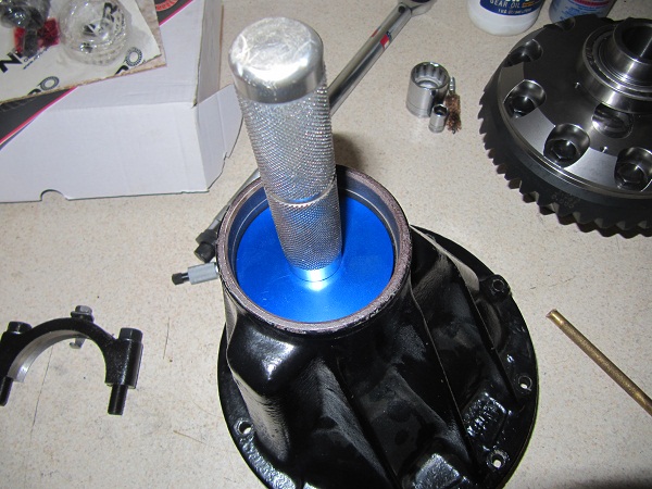
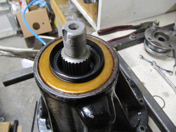
Now remove the Pinion nut and flange for the last time. No need to press the pinion out. We only need to install the pinion seal. Add some oil to the seal lip to prevent a dry start.

Now using a hammer, evenly and gently tap the seal in. Making sure not to twist or warp it.
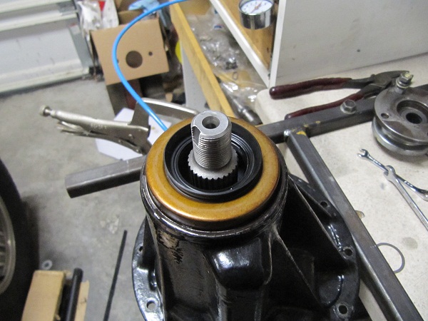
Add a small amout of Gray RTV to the inside splines of the flange and install it. Don't over do it with the RTV. A little goes along way.

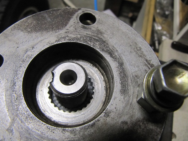
Notice the RTV gave us a good seal.
Now install the flange washer, add some locktight read to the pinion nut and torque it down to between 120 -150 ft lbs.

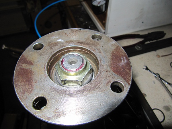
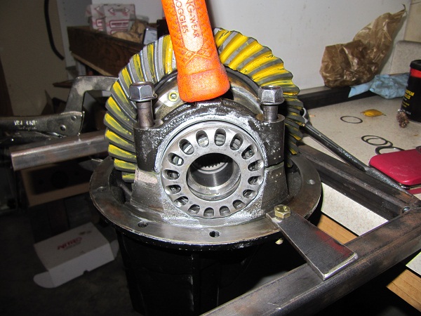
And using a chisel and hammer ding the nut.
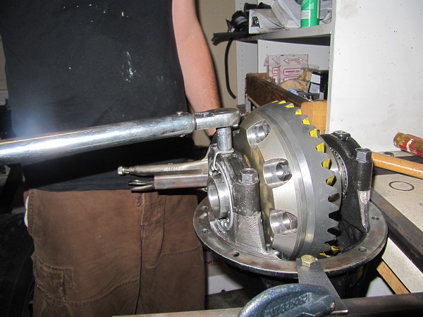
Pinion DONE! Now reinstall the ring gear assembly and set up the proper backlash as described above. The only difference this time, is you want atleast 120 ft lbs of toque on the adjuster nuts. Don't be shy use some force!. This preload not only keeps the bearings happy but preloads the housing itself, keeping deflection and movement down when the third member is under load.
Next torque the carrier bearing caps down to 75 ft lbs.
After everything recheck your backlash and pattern. It should not have moved. Rotate the gear and check the backlash from several different teeth around thh gear.
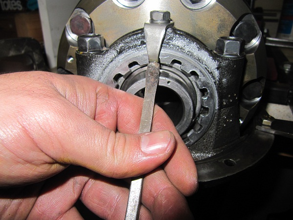
Install the locking clips into the adjuster nuts and torque to 10 ft lbs.
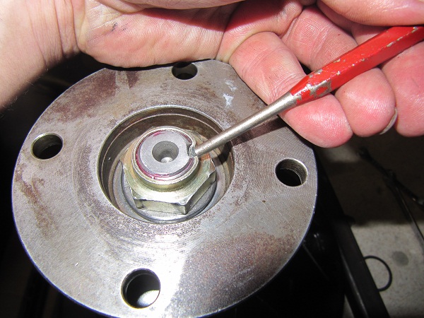
On an ARB locker make sure the locking tab is in the top of the adjuster nut. I use a punch or flat blad screwdriver and tap it up.
Oil and install the ARB air seal. Make sure not to force it. I use a gentle twisting to get it on. Make sure it sits flush with the locker. Also make sure the locking tab is not touching the ARB air seal.
Install the retainer clip using a screwdriver.

Next route the airline as shown in the ARB manual.


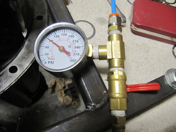
Using my homemade tester it held 90 PSI.
Install into your axle, add oil and follow the manufacturing instruction for brake in procedure.
DONE! hope you enjoyed my little write-up! Thanks Zippo